|
|
Volume Interior TestingOr: Deconstructive Solid Geometry
For several cases I've found a need to find whether a series of points lies within a 3D surface or not: What I've done is implemented a general method for determining the interior points of an object when supplied the triangles that make up the skin, and afterwards I can assume uniform density and use that volume for other tasks. Given that a bounding volume has been found, the idea is to break the volume up into equally spaced points, and then test each point to see if it is inside or outside of the object: if it is inside put it into a vector. The vector is the volume of the object, and is only as accurate as the testing points are close together. Determining whether a point is in the interior or not sounds fairly easily, but has a few snags. If a line is drawn that passes through the test point and the rest of the volume, and it intersects the object anywhere, there's a chance the point is on the interior. Take a look at the 2d diagram: 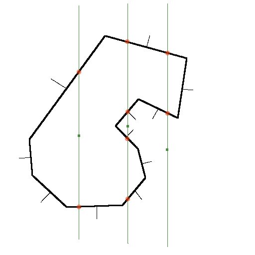
(It'll help with optimization later on to have all the test lines axis aligned) All three test lines intersect the object somewhere (and in even numbers of times as well, or else the bounding volume is screwed up or we've let an edge/point intersection pass through). Also note the orientation of the thinner normal lines. The rightmost point has two points of intersection, but both are above the test point, so it is discounted. The left point has two intersection, one below and one above. To make absolutely sure the test point is inside take the dot product of the intersected surface's normal and a line that originates at the test point and passes through the same intersection point- that is, both normals have to be facing away from the test point. The middle test point suggest a few more tests to be done: the intersection points have to be sorted to yield the closest above and the closest below, so in this case both of the normals are facing towards the point and it is outside the object.
With all the test point processed, plot the contents of the interior vector as well as the regular object, and have controls that can turn the drawing of either on or off. Probably a few points are going to sit on the outside of the object, but if they're reasonably close to the surface no big deal. It's obvious that it's working when the points provide a decent silhouette of the surface object. The first iteration of the program I got working takes an extremely long amount of time for objects with a few hundred triangles. Extremely convoluted non-convex objects slow this down even more. Most triangles can be discarded for a test point if the corners don't span the test point (axis alignment is key here). It's important to have a simple test object initially, and of course get the thing working before attempting much optimization. Here's a convoluted model I made in Wings with dense testing points. There are some interesting rendering possbilities here, attached a tiny billboard to each point for instance, or just gaze at the moire patterns the points alone make. 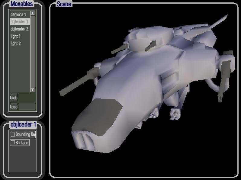
The skin above and the volume points (voxels I guess if I made them space filling) below. The gun barrels are hollow and are almost excluded by the volume testing for their thinness. Those lines are just visual artifacts, not internal structures. 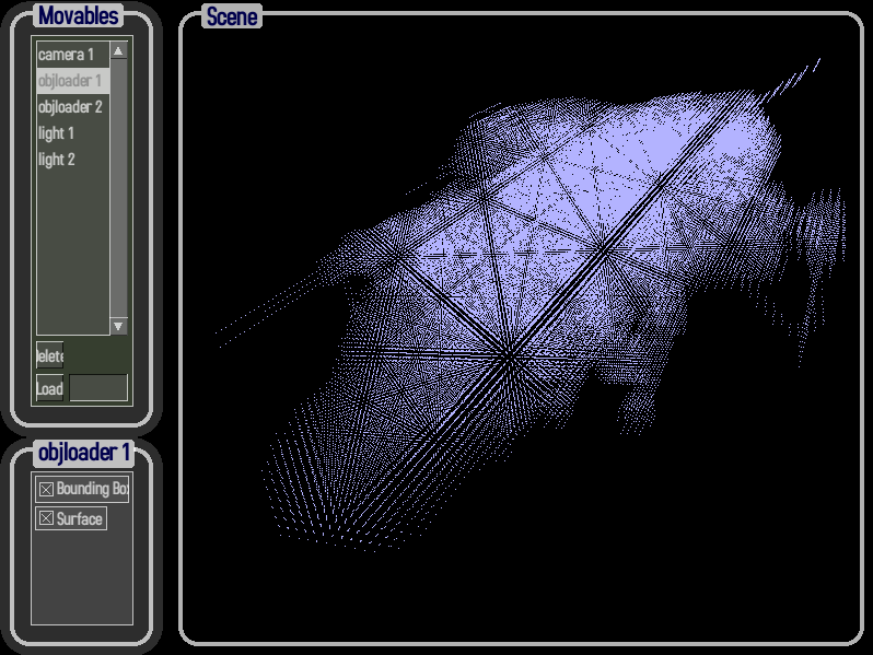
That's the GLGooey OpenGL gui running the listboxes and checkboxes. It's even cooler to watch it rotate around in real time...so here's a sample windows executable volumeInterior.zip. 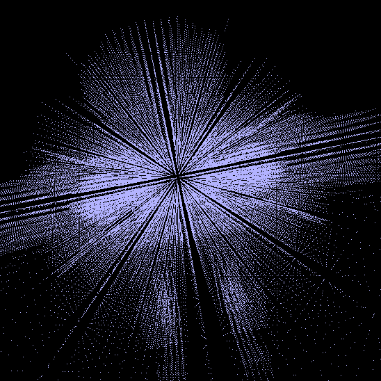
Test point selection
If the only purpose is to find the moment of inertia, then it is sufficient to select evenly spaced test points (in the cartesian coordinate system) in a triple for-loop like this:
But for creating an internal structure, other coordinate systems may be desirable. But for a mostly cubical object, the above works well: 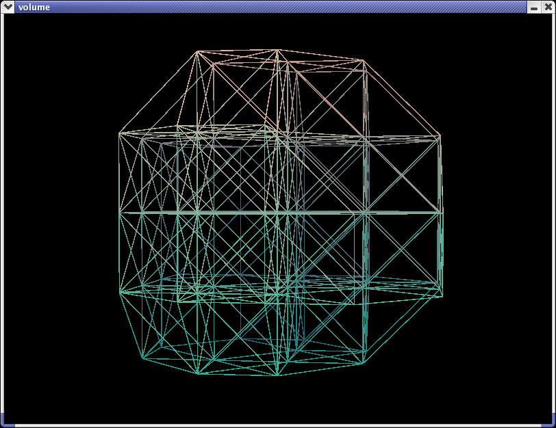
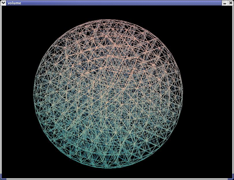
With increased test point density, the true shape emerges: 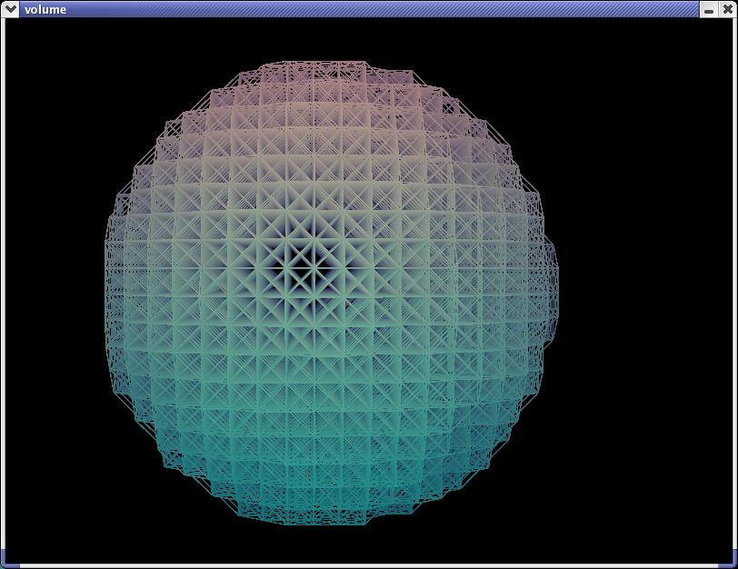
But we can do better without that density by altering the coordinate system, here's cylindrical: 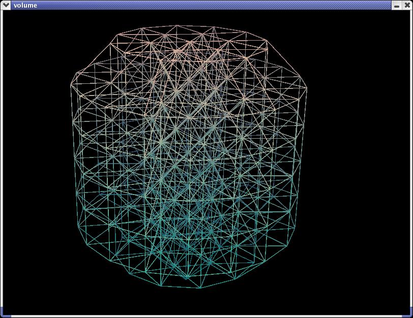
Since the object we're dealing with is a sphere, why not go all out and adopt a spherical coordinate system: 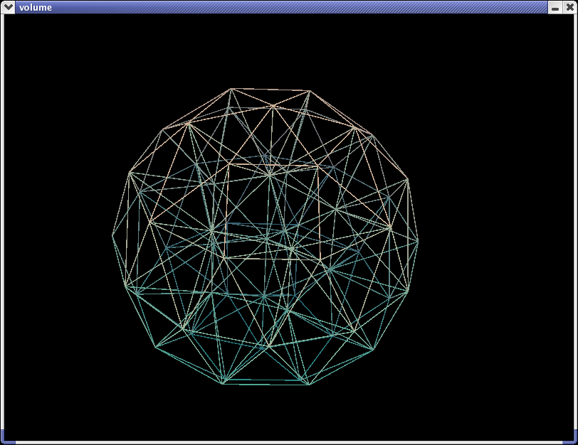
Here's a cube that's been approximated with the spherical system: 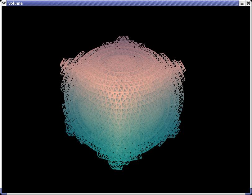
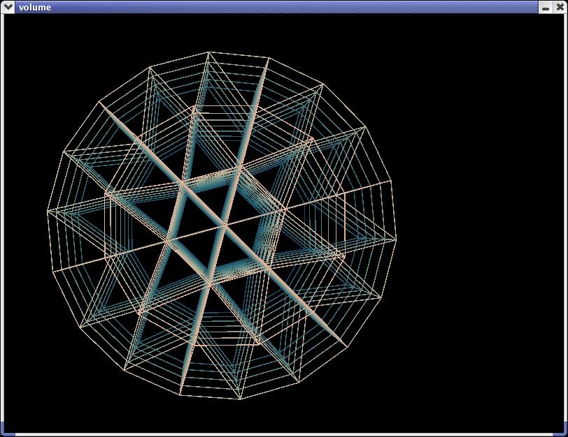
Cylindrical Test Point Spacing The test point algorithm for the cylindrical case is pretty easy. For each concentric layer (each of which is the step size further out from the last), we want a number of testpoints with equal spacing- and spacing approximately equal to the step size. So the circumference of a layer is 2*pi*R, and R is an integer multiple of the step size, so circumference = 2*pi*layerNumber*stepSize. The spacing ~ step, so we can find the number of test points around a given layer by dividing the circumference by the step size. The number of test points needs to be an integer, so round that down- then divide the circumference by this value to find the spacing to be used. Since the step size is in the numerator and denominator both, it divides out, and we're left with rounding down 2*pi*layerNumber. Although it isn't correct, I've just approximated that to 6*layerNumber (although for higher layerNumbers this is no longer as close, it makes a prettier pattern). Here's what it looks like in code:
Spherical Test Point Spacing The algorithm here is a bit more involved, but follow from the cylindrical case. Now theta also defines the radius at the layer in question, so take the equation for the radius, stepSize divides out, round down the result (casting into int does this in C and C++, though I'm not sure if that is defined behavior or implementation specific). It's easier to deal with the spacing in radians (rather than actual resulting spacing), so 2*pi divided by previous rounded value is what we seek. Using the same rule of thumb as for cylindrical give use the theta step size. Theta is the angle from the north polar axis, and phi is the angle from where the x-axis should be. I adopted this convention from an electromagnetics text, any other should work as well if it stays consistent.
Sample Windows and Linux (RH 8.0 libs) executables with test .obj files. OpenGL and SDL libraries required. Please contact me with any difficulties getting these to work. A CS grad student's rigid body tutorial, with some psuedo code and content similar to this page. Copyright © 2002-2003 Lucas W |